This project adapts the existing Invisible Drum Set—originally implemented with an Arduino Nano and BNO055 IMU sensor—onto the E155 hardware platform, consisting of an STM32 MCU and UPduino FPGA. It enables playing virtual drums through air gestures detected by the IMU, with real-time audio synthesis and low latency.
Invisible Drumset
A dual-hand embedded system that enables playing virtual drums through air gestures detected by BNO085 IMU sensors. Built for E155 Final Project using Arduino ESP32, FPGA, and STM32 MCU for real-time gesture recognition and low-latency audio synthesis.
Invisible Drumset Demonstration Video
Abstract
System Overview
Each drumstick is designed as a fully independent embedded system, containing its own BNO085 sensor, Arduino Nano ESP32, FPGA, and STM32 microcontroller. This distributed architecture ensures that the left and right sticks remain electrically and logically isolated — improving robustness, reducing latency, and making the system scalable to additional sticks in the future.
The data pipeline in each stick relies on multiple communication protocols between its hardware components. The BNO085 sensor communicates with the Arduino Nano ESP32 using the I²C protocol, with the high-level SHTP protocol layered on top to enable structured transfer of fused motion data. Once the sensor data is received by the ESP32, it is forwarded to the FPGA over an SPI interface, where the FPGA operates as the SPI slave and the ESP32 serves as the SPI master. On the FPGA, the data is packaged into a custom packet format and relayed to the MCU for trigger processing.
From there, the FPGA sends the packaged data to the STM32 microcontroller through a second SPI link, again with the FPGA acting as the slave and the STM32 as the master. The microcontroller performs gesture recognition to detect drumming motions, and the resulting sound IDs (0–7) are output through a digital-to-analog converter (DAC) to drive a speaker that plays the correct drum sound.
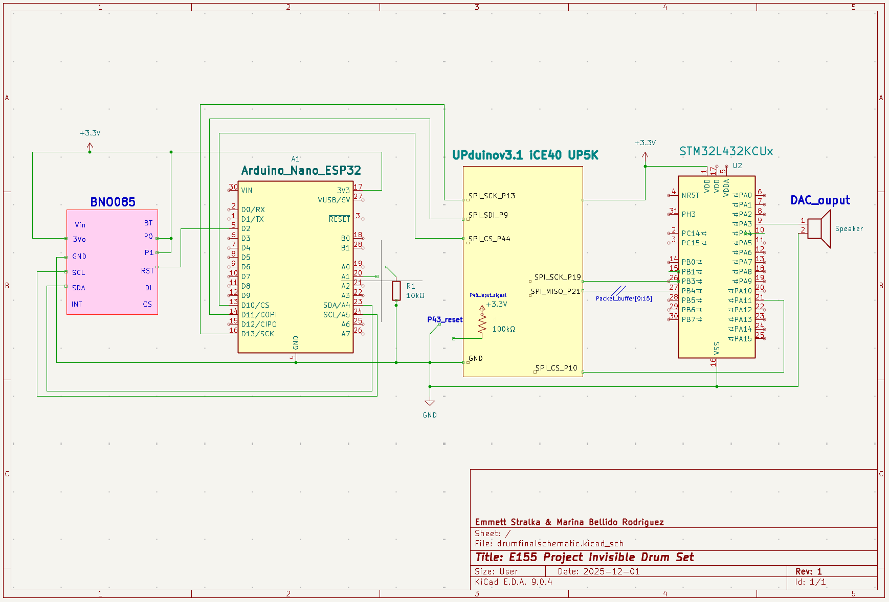
System Schematic
Final Dual-Stick Embedded System Prototype
Packet Format
Each package is passed as:
- • Byte 0: Header (0xAA)
- • Bytes 1-2: Roll (int16_t, MSB first) - Euler angle scaled by 100
- • Bytes 3-4: Pitch (int16_t, MSB first) - Euler angle scaled by 100
- • Bytes 5-6: Yaw (int16_t, MSB first) - Euler angle scaled by 100
- • Bytes 7-8: Gyro X (int16_t, MSB first) - scaled by 2000
- • Bytes 9-10: Gyro Y (int16_t, MSB first) - scaled by 2000
- • Bytes 11-12: Gyro Z (int16_t, MSB first) - scaled by 2000
- • Byte 13: Flags (bit 0 = Euler valid, bit 1 = Gyro valid)
- • Bytes 14-15: Reserved (0x00)
Architecture
FPGA Design
Initially, we attempted to configure the BNO085 sensors directly from the FPGA using an 11-state finite state machine (FSM) with encoding logic implemented using DSP blocks. This approach aimed to handle the Sensor Hub Transport Protocol (SHTP) communication directly on the FPGA, including sensor initialization, command encoding, and data packet parsing. While this implementation successfully extracted data from the sensors, the approach proved unreliable in practice.
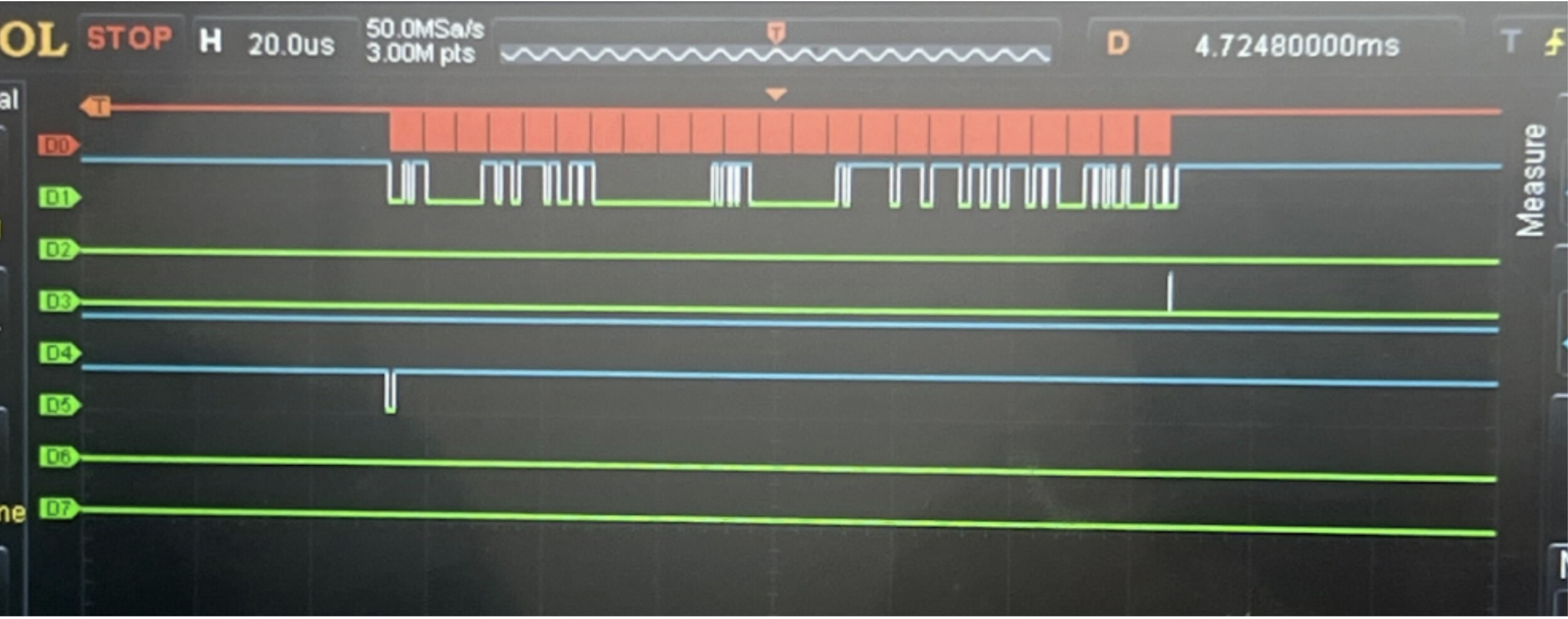
FPGA data output trace on Logic Analyzer with FPGA configuration and initialization
Given the reliability challenges with the FPGA-based sensor configuration, we transitioned to a more reliable hybrid architecture that leverages the strengths of each component:
- • Arduino ESP32: Handles sensor configuration and data acquisition using the mature Adafruit_BNO08x library, which provides robust SHTP protocol handling and reliable sensor communication over I²C.
- • FPGA: Receives pre-processed sensor data from the Arduino via SPI and packages it into a custom transmission format optimized for the MCU interface.
- • STM32 MCU: Decodes the packaged data packets from the FPGA, identifies drum triggers based on gesture patterns, and outputs audio samples through the DAC to drive the speaker.
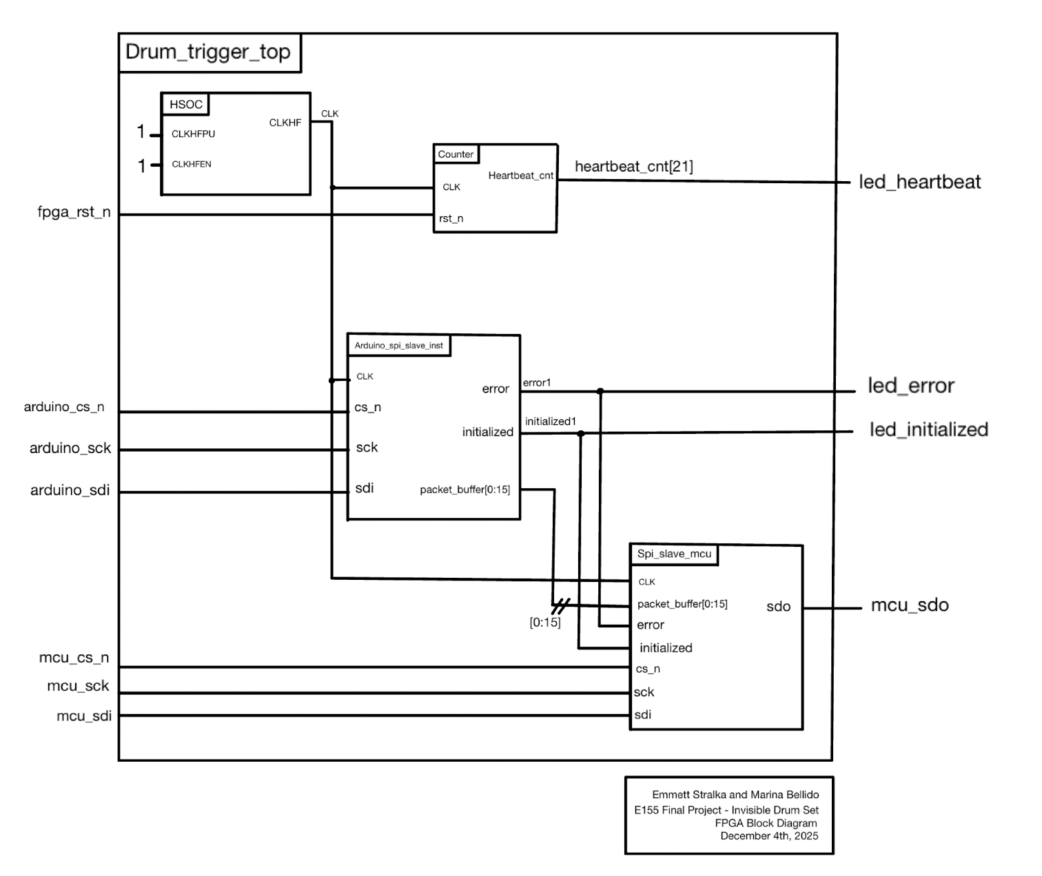
FPGA Top Module
Key Modules:
- •
arduino_spi_slave.sv— Receives 16-byte packets from Arduino via SPI, buffers and converts quaternion to Euler angles - •
spi_slave_mcu.sv— Sends packet buffer to MCU via SPI as read-only slave - •
drum_trigger_top.sv— Top-level module connecting both SPI slaves
MCU Design
The STM32 microcontroller decodes the packaged data packets from the FPGA, identifies drum triggers based on gesture patterns using yaw zones, pitch thresholds, and gyroscope readings, and outputs audio samples through the DAC to drive the speaker.
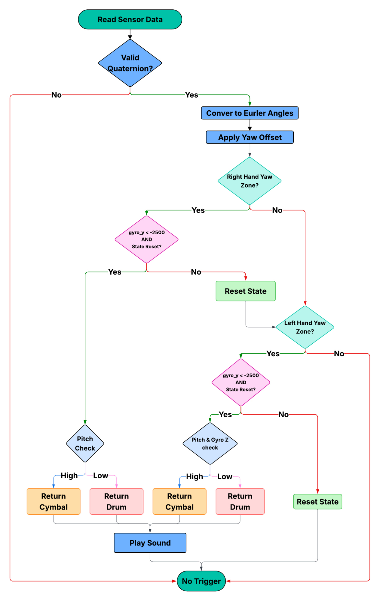
MCU Main Control Loop Flowchart
Detection Logic: The system uses predefined zones based on Euler angles (yaw, pitch) and gyroscope readings to detect 8 different drum sounds:
- • 0x00: Snare
- • 0x01: Hi-Hat
- • 0x02: Kick (button)
- • 0x03: High Tom
- • 0x04: Mid Tom
- • 0x05: Crash
- • 0x06: Ride
- • 0x07: Floor Tom
Hardware
BNO085 IMU Sensor
The BNO085 is a 9-axis intelligent IMU that integrates an accelerometer, gyroscope, and magnetometer with an onboard sensor-fusion processor. It communicates through the Sensor Hub Transport Protocol (SHTP) over I²C, providing fused orientation data like quaternions and Euler angles.
Arduino Nano ESP32
The Arduino Nano ESP32 handles sensor configuration and data acquisition using the Adafruit_BNO08x library, which provides robust SHTP protocol handling and reliable sensor communication over I²C. The ESP32 forwards processed motion data to the FPGA via SPI.
Results
Working Protocols
I²C Data Transmission between BNO085 - Arduino
Before validating the SPI interface, the correct operation of the BNO085 sensor stream was confirmed using the Arduino Serial Monitor. The Arduino receives fused motion data from SHTP Channel 2, including Euler angles and gyroscope measurements.
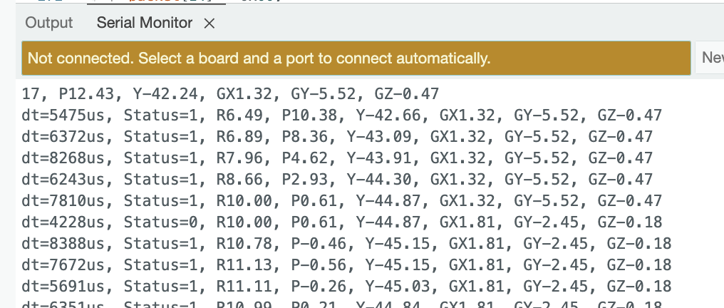
Arduino Serial Monitor Sensor Data
SPI Data Transmission between ESP32 - FPGA
To verify correct data transfer between the Arduino ESP32 and the FPGA, the SPI bus was monitored using a logic analyzer. The captured waveform confirms that the expected byte sequence is transmitted from the Arduino to the FPGA when new motion data is available.
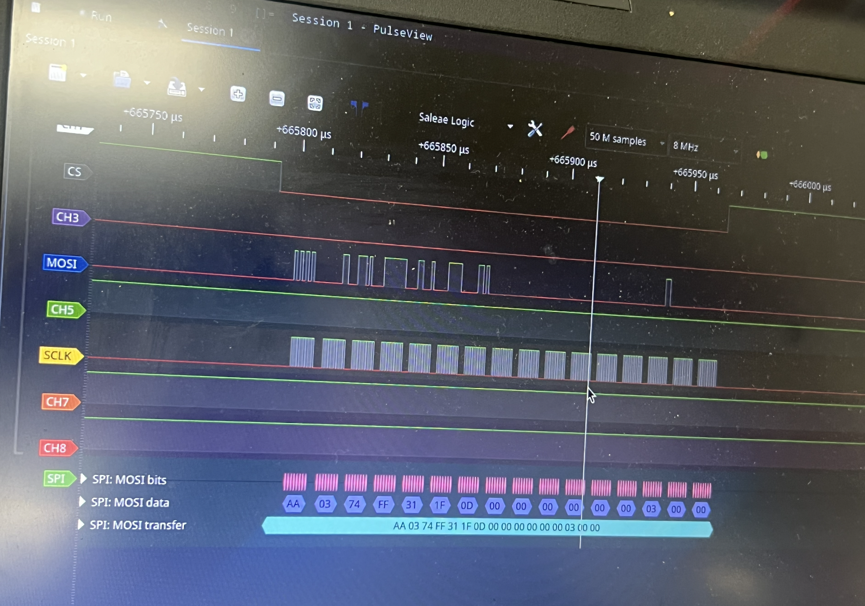
Logic Analyzer with outputted SPI Protocol
SPI Data Transmission between FPGA - MCU
To verify correct data transfer between the FPGA and the MCU, the SPI bus was monitored using a test bench and a logic analyzer. The MCU successfully receives the formatted 16-byte packets transmitted through the FPGA.
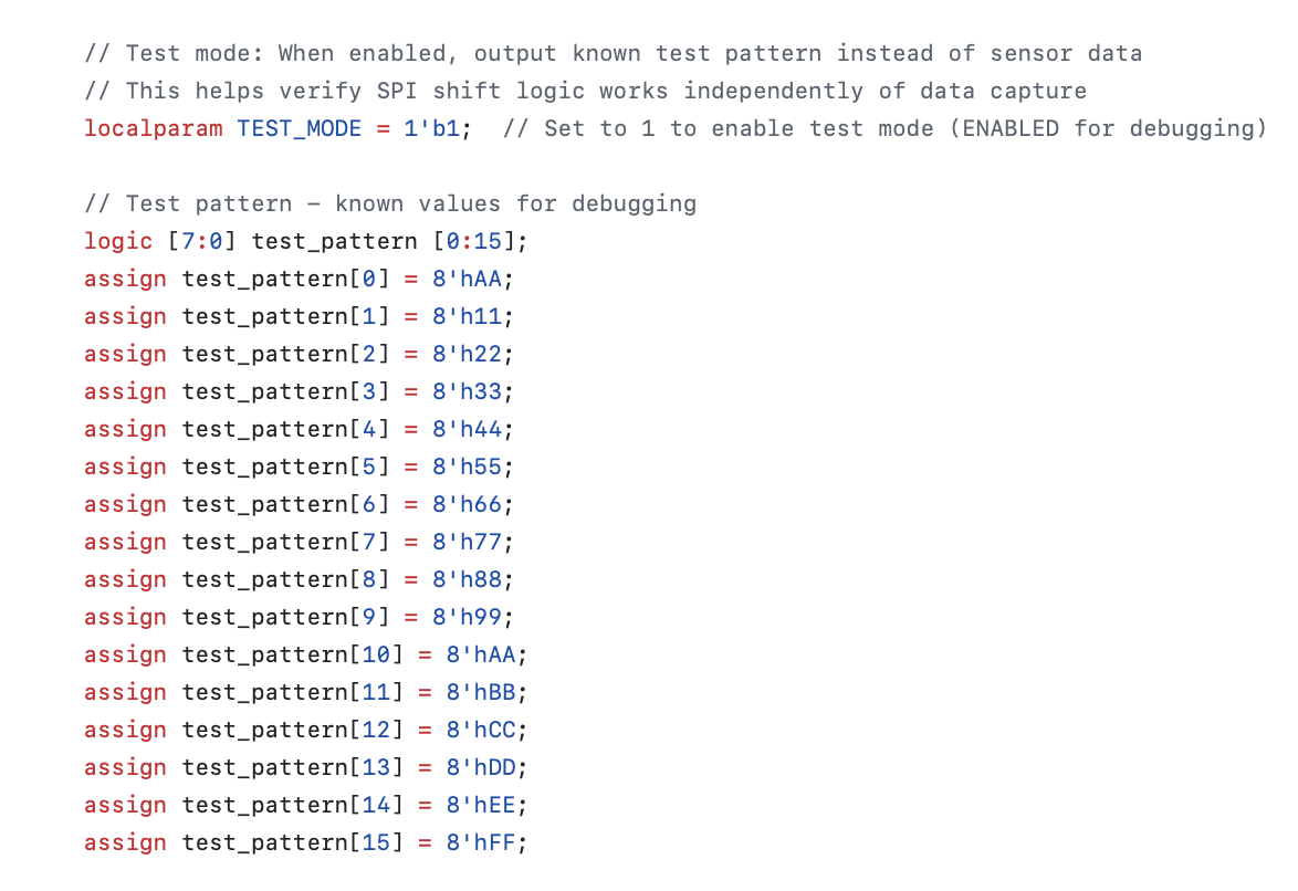
spi_slave_mcu test pattern
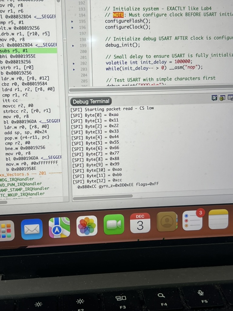
Segger Debug Terminal outputting MCU receiving the correct test pattern
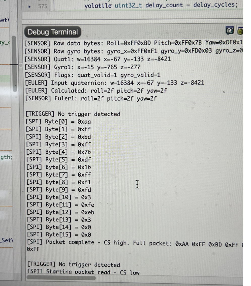
MCU Debug Terminal output displaying the 16-byte SPI packet received from the FPGA
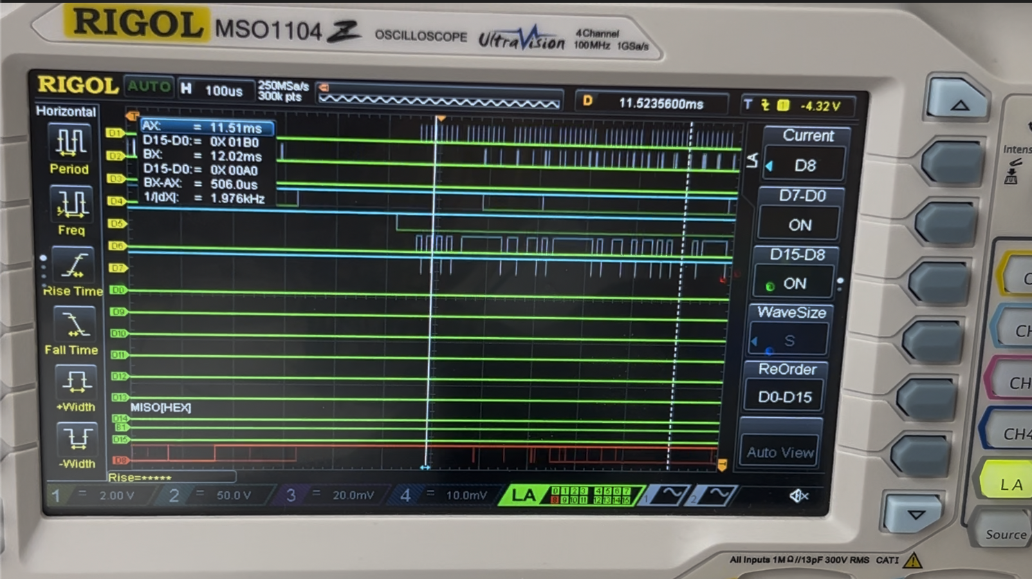
Logic Analyzer showcasing the SPI Protocol
DAC Working
To verify audio output capability and confirm correct DAC initialization, the MCU firmware begins by sequentially playing each stored drum sample at startup. This provides a functional baseline test proving that the audio subsystem is fully operational before real-time trigger detection begins.
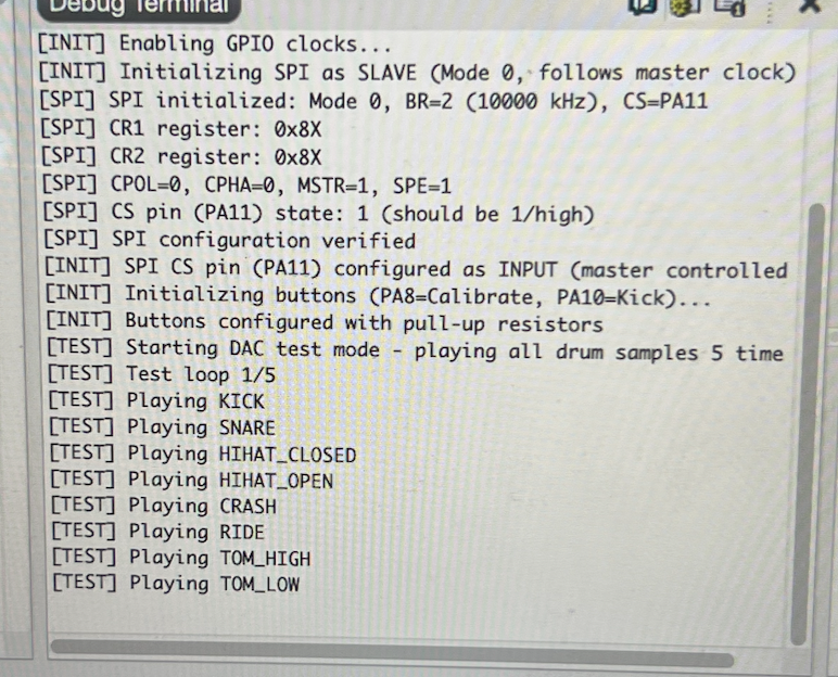
Initialization of all drum sounds outputted by the DAC
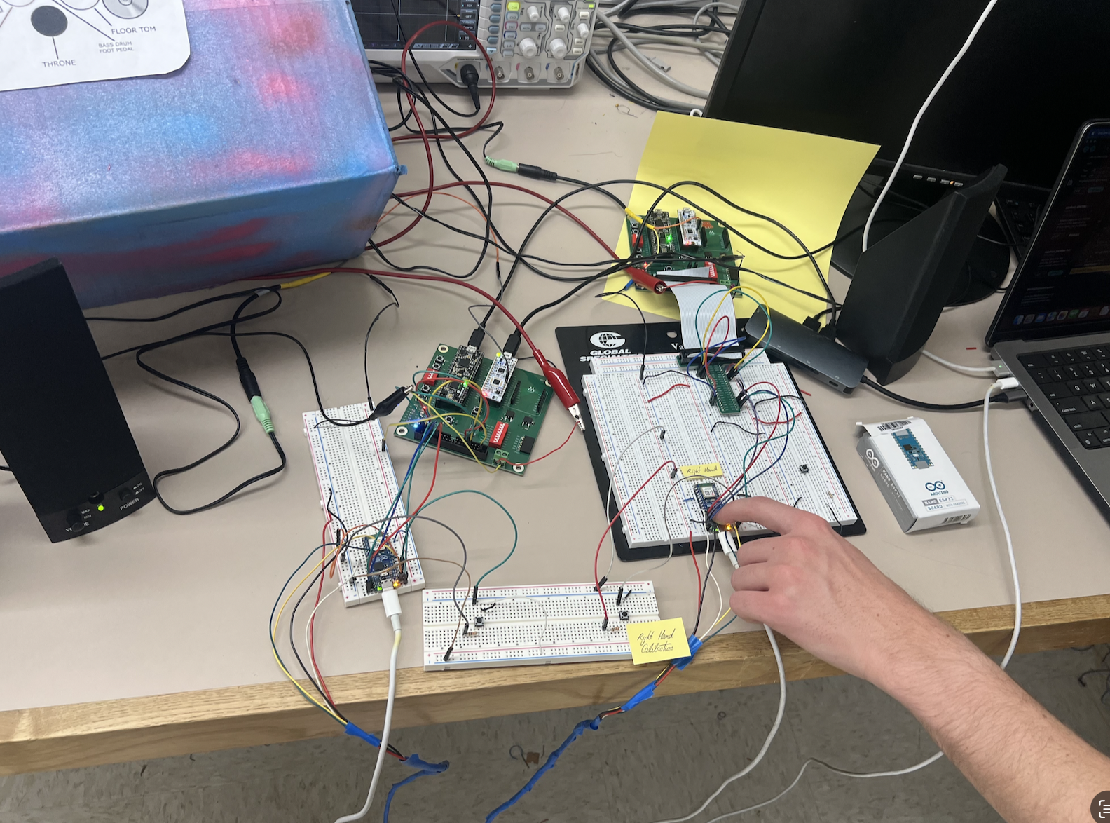
Final Prototype
Full Dual-Stick Embedded System Prototype
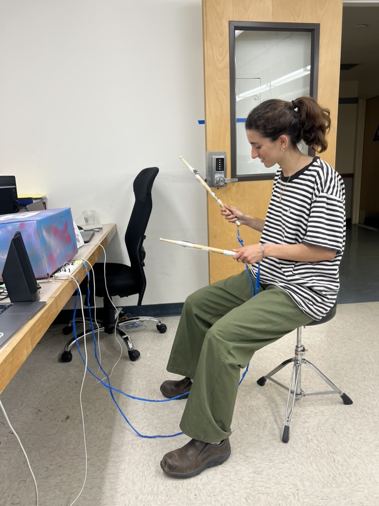
User Testing of the Dual-Stick Invisible Drum Set Prototype
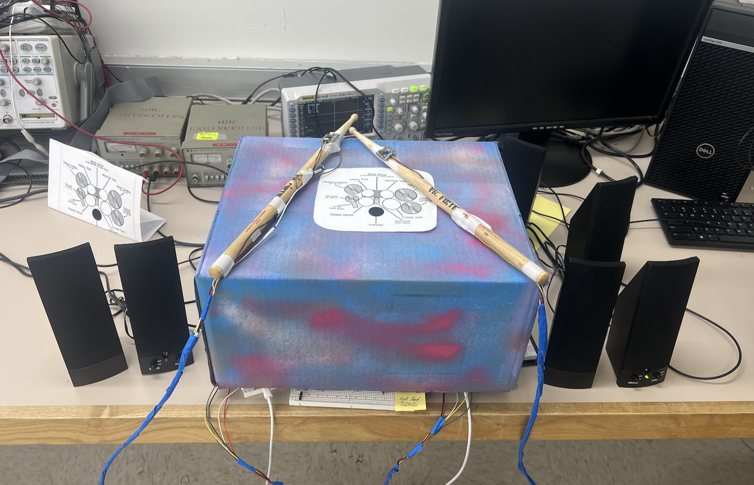
Final Prototype Assembly with Integrated Speaker Output
Code Repository
The complete source code, including FPGA SystemVerilog modules, MCU C code, Arduino/ESP32 code, testbenches, and documentation, is available on GitHub.
View on GitHub FPGA Source Code MCU Source Code